Cheap CT Clamp Based Energy Monitoring
Within the last couple of months the Home Automation Software I use, Home Assistant (HASSIO) has added some new Energy monitoring features which look really handy.
It had a few recommended methods for monitoring power, being:
- A data protocol on meters that seem based primarily in Netherlands, Belgium and Luxembourg. So basically useless to me being in the UK.
- A DIY solution where you put a light sensor onto the blinking LED on the meter, this LED blinks every time you use X of a unit.
- A DIY Solution of a Current Clamp on the mains cables from the meter.
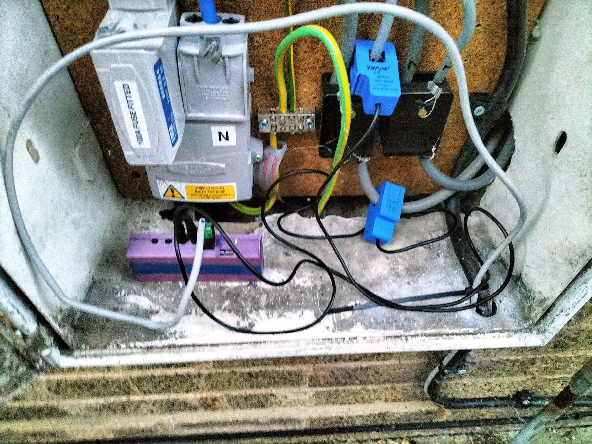
I decided to go for the third option as the parts were quite easy to get hold of, plus I could use two clamps, one on the feed into the house and the other onto the feed to my EV charger.
The main issue I found with this was routing a power source for the microcontroller to the meter box, my meter is outside however luckily I had a 12V cable running to something else near the meter so ran a 12V cable into the meter cabinet.
The BOM
The BOM was quite low
You'll need:
- A CT Clamp Sensor, the most recommended is these
SCT-013-000sensors. They're less than £10 each from eBay or even less than £5 from Aliexpress if you don't mind the wait. - A Wemos D1, you could technically use any ESP8266 but I chose one of these for ease.
- Some circuitry to connect the CT Clamp to the ESP8266, this typically is a capacitor, some resistors plus a connector for the clamp.
For the last one I found an eBay seller that was already selling boards, I originally ordered just one of the basic boards that supports one sensor and is powered by the ESP8266 at https://www.ebay.co.uk/itm/133077015640 .
However later on I then switched to the 4 channel version that has an ADC at https://www.ebay.co.uk/itm/133377327840 , this also was powered by 12V so resolved the part too.
More accurate Voltage Source
One flaw with the CT method is that you need to provide it with a voltage, some tutorials say to just manually set this, however while our mains should be 230V in the UK it can vary quite a range all the way from 240 to 247V throughout today.

I have a few sockets in my house which monitor and report the voltage to, I calibrated one that's on 24/7 as close as I could and then noted down the entity this shows up on in HASSIO.
Setting it up
Once all the parts arrived the hardware assembly was simple, just push the Wemos onto the carrier board, connected the two current clamps to the board and it was ready to go.
Next I flashed ESPHome onto it, here's the code I used. This code will work for the first CT sensor on the board which has 4 sockets and the I2C ADC, you'll have to copy and edit the code for the other 3 sockets.
esphome:
  name: house_power
  platform: ESP8266
  board: d1_mini

# Enable logging
logger:

# Enable Home Assistant API
api:

ota:
  password: "<generatedbyesphome>"

wifi:
  networks:
  - ssid: "<WIFI_SSID>"
    password: "<WIFI_PASSWORD>"

  # Enable fallback hotspot (captive portal) in case wifi connection fails
  ap:
    ssid: "House_power Fallback Hotspot"
    password: "<WIFI_FALLBACK>"

captive_portal:

i2c:
  sda: 4
  scl: 5
  scan: true
  id: bus_a

ads1115:
  - address: 0x48

sensor:
  - platform: homeassistant
    name: "Voltage From Home Assistant"
    entity_id: sensor.<VOLTAGE_ENTITY_HERE>
    id: home_voltage

  - platform: total_daily_energy
    name: "import_ct_total"
    power_id: import_live
    unit_of_measurement: "kWh"
    id: import_ct_total


  - platform: ct_clamp
    sensor: adc_sensor0
    name: "import_live"
    id: import_live
    update_interval: 15s
    filters:
      - calibrate_linear:
        - 0 -> 0
        - 0.01764 -> 2.479
      - lambda: return x * id(home_voltage).state / 1000;
    unit_of_measurement: "kw"


  # Example source sensor
  - platform: ads1115
    multiplexer: 'A0_GND'
    gain: 6.144
    name: "ADS1115 Channel A0-GND"
    id: adc_sensor0

time:
  - platform: sntp
    id: my_time
There's a few variables you'll need to change if you use the above which are:
- Wi-Fi SSID & Password along with Fallback Password
- A new ESPHome Key - Typically generated by it.
- The entity in HASSIO you'll use for voltage.
Finally you'll then have to calibrate the sensors using the calibrate_linear function. I did this by adjusting the value based on what my smart meter was reading.
Once this was done, I had to just approve the ESPHome integration in HASSIO and it worked!

Final Overview & Flaw
The above CT clamp method works fairly well, the hardest part was getting power to the ESP8266.
However one unfortunate thing is that the above method doesn't work to monitor exporting power to the grid, while the clamp sensors have arrows to indicate which way round they monitor. For this to work with AC power you typically require a more complicated breakout board and ideally a mains socket within reach of the breakout board.
I'll work on another solution for the whole home power monitoring, however will be keeping a clamp on the feed to my car charger and when we get solar installed soon setup another on the power generated by the solar inverter.