EV Charger Hacking Success!

Backstory
We’re in the process of switching to our new energy supplier’s (Octopus) EV Tarrif. Of which the daytime rate of electric is around the same as other tarrifs at 14p per unit, but for 4 hours a night this reduces down to 5p per unit. Roughly taking my yearly charging down from £200 to £70.
My car is smart enough to have a timer built in but the issue is, this can sometimes cost £18 a year to have this feature in my Zoe. But the main issue is that when charging in public you have to remember to turn it off and then turn it back on. Compared to some EVs you have to go through a few menus each time.
Now the charger I brought advertises itself as a “smart” charger with this being one of the features that smart chargers do. But mine doesn’t yet…
For reference I brought this model of charger as it worked out cheaper with the extra work I needed than the “dumb” chargers. However I think the dumb charger would have actually been easier to hack as these use a resistor to set the maximum charge current and by having a relay connect a lower value resistor to the module which would effectively disable the controller. Then connect a different resistor to set the correct amperage.
I did consider a DIY EVSE project however in the UK there’s quite strict electrical regulations, If I did buy the parts for a DIY unit and the cable it would have been around £500 in materials. And while I would have been fine wiring in the cables and routing them to IET standards I would have to get an electrician to then test and do the final connection to the electric supply. This would have cost more than the installation as while the installation was over £1000, the UK Government funded £500 of it of which my DIY install would not have been allowed the £500 grant.
Disclaimer!
High voltage electronics are in play here! This charger specifically should be treated as if the low voltage circuit is also live!
Isolate and lock out the RCBO / Isolation switch before touching any circuitry.
Throughout testing I did test the +12v Rail in reference to Ground and Neutral and was showing around 50V difference. So each time I touched the unit I first isolated it at the RCBO.
Investigating
As this is the summary I won’t go into much detail of the investigative work. I was originally hoping a hidden API would be available, or once opened up I would find some headers that would easily enable what I wanted.
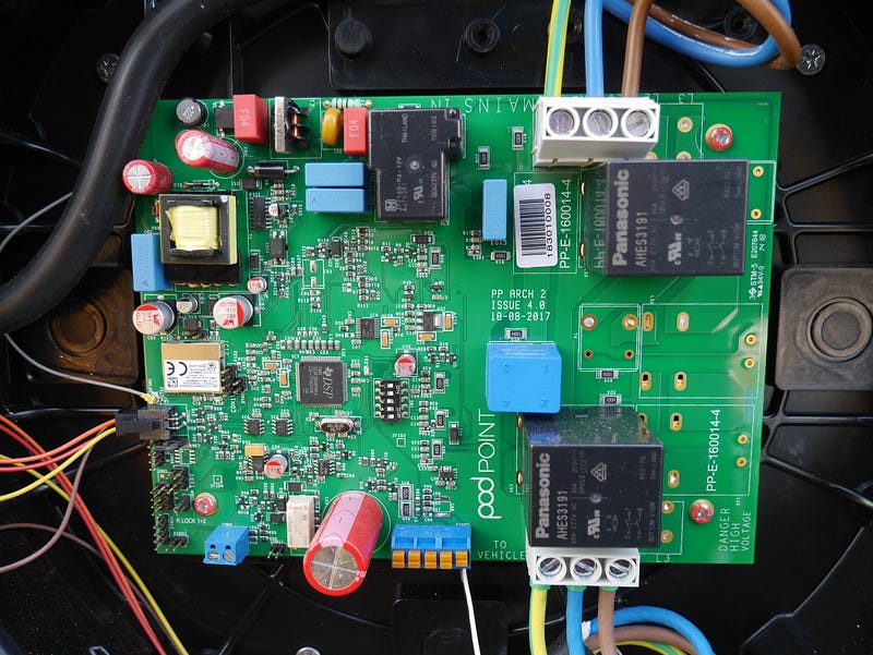
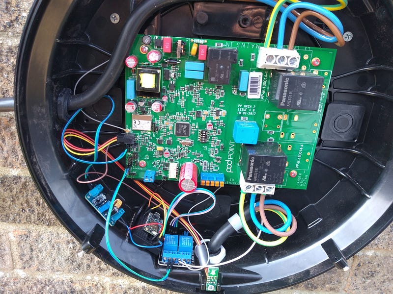
Once I opened it up I just took a lot of high quality photos which can be seen at https://photos.app.goo.gl/GA48ju3XvypGt1BD8 . I posted these on twitter of which I had 2 people message me that the Isolation of the High and Low Voltage side looked poor and that the low voltage side would potentially have the ability to shock me.
The UART port of my charger from my initial testing ignored any serial data and only sent back when charging the real time values of how many KW of electric was being measured on each phase.
Once I decided the TI MCU inside was a bit more complicated than I wanted to program I decided to try other leads, I first thought about using the LOCK header on the unit.
The LOCK header is two pins that can be connected by a key lock as the name implies. This is so that someone else can’t come along and use your charger however I was’t worried about this so didn’t get one.
But I thought what if I essentially locked the unit while charging to end it, and unlock it to start charging.
This worked to end a charge, however when I unlocked the unit the charge did not resume in my testing so wasn’t suitable.
I then posted on SpeakEV about my postings and within discussion originally looked at connecting my own MCU between the car and evse’s Control Pilot Signal. This is a mixture of resistors to tell the charger if the car can charge or not and a PWM Signal back to tell the car the speed it can charge at.
But then someone said instead of intercepting the signal as I only wanted to control the timing to just connect and disconnect the control pilot. Even easier! Just a simple relay. Throughout discussion someone said the car might throw errors if the CP is just disconnected mid charging.
The solution to this was to also use the lock feature by locking the charger first then disconnecting the CP.
Hacking!
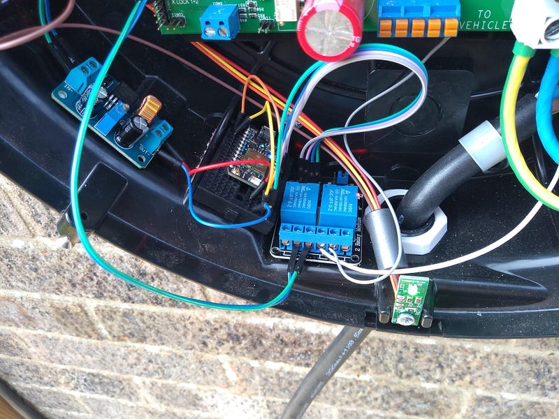
It was then time to implement it, I ordered a cheap 5V Dual Relay module off eBay as this was only low voltage being controlled.
Then the hardest part, what board to use? An arduino was too simple as I wanted it to have connectivity, after looking through my box of boards including Raspberry Pi, Onion Omega, Arduinos of lots of varieties and more I settled on the Particle Photon I have had in its box since backing it on Kickstarter.
The great thing is that it can be programmed via a Web IDE but also has IFTTT integration making it ideal.
Using example code I whipped up a quick piece of code which has a single function of which if it is sent “on” it’ll turn the charger on and “off” will turn the charger off. (Code found at https://paste.ubuntu.com/p/vzzvFcXx9K/)
I wired this up to the relay module and then one relay to connect the two pins of the lock function (In a normally closed configuration as I want the relay to only be turned on while charging). And the control pilot in a normally open configuration so when turned on it’ll connect.
I then wired it all up with jumper wires and powered it from the charger’s 12V rail itself. Once again isolating the charger before plugging any headers in.
And then it was completed! I turned the charger on and tested it without the cover on to check the LEDs on the relays were acting correct and it seems to be working fine.
Long term testing is needed but so far it’s working great.
Finally to have it turn on and off with the correct times I use IFTTT with the day time option.
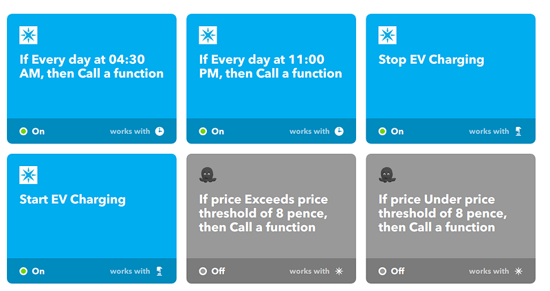
There’s also two other reasons for using IFTTT, As shown I’m also using the button widget functions for manual overrides such as if I need a further top up before a long journey.
However I would also need to manually override it as well for the preconditioning as it’s a simple button on my phone it’s not an issue at all.
But further into it, in a years time we might consider switching to our electric supplier’s “Agile” tariff. This is a tariff that has no fixed price and changes every half an hour and as you can see has IFTTT integration! I’ve programmed it in ready but won’t enable it yet. While usually overnight is cheapest I have seen a few times where the daytime is cheaper than nighttime thanks to solar and wind.
Where next?
While I doubt we’ll get solar panels as the payoff is quite a long time even with charging my car, the next steps may be if I feel like it creating a PCB which does the CP Interception instead, this way I can control the speed based on solar if I feel like it. It’d also neaten it up more.
Ideally the manufacturer of my charge point (Podpoint) would enable an API for users to be able to control their chargers or even better IFTTT integration to make it even easier.
Update
Just a quick update written on the 25th of Apr.
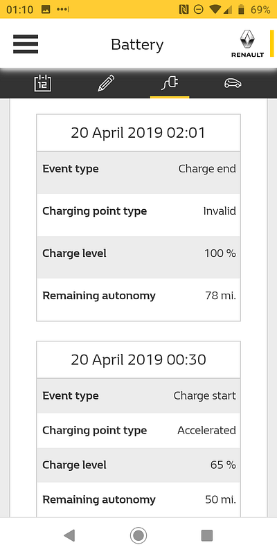
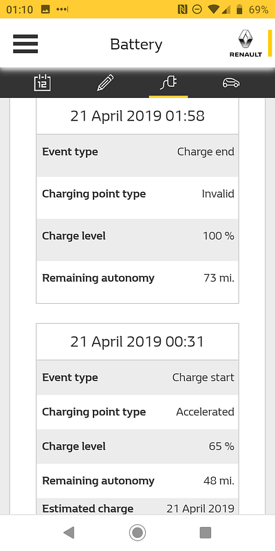
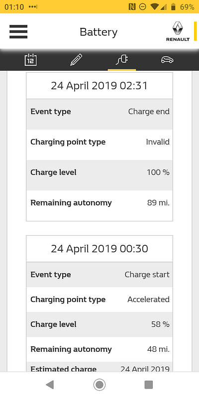
So far it’s been working fairly reliably with the last 3 charges starting prompt at 00:30, the finishing time has been before the electricity cut off however it has been shutting off correctly.
For my car even from empty this 4 hour period is usually enough to charge it from 0% to 100% however in reality it never gets that low.
And here’s the screenshots of the Car’s charge logs.