Designing a New Outdoor LoRa Gateway
It's been a while since I did any electronics work as my job involves mostly software and customer support. However recently I've wanted to do a few electronics projects where having a LoRa Gateway on TTN running again would be handy.
While I have pieces of old gateways I've worked on, none of them quite are what I'm looking for now either being too basic or too complicated.
The Goal
So my Goal was to build a new LoRa gateway that has the following specs:
- Outdoor - I wanted this one to be an outdoor unit. The indoor market is now quite competitively filled but I felt the outdoor one isn't quite full yet.
- Lightweightish - The other issue with quite a few outdoor solutions is that they are HEAVY. So the goal is to be small and relatively lightweight.
- Keep It Simple Stupid - It needs to be no thrills, just a basic 8 Channel LoRa gateway powered via POE and nothing else. No 4G backup, more channels, less channels, extra sensors, solar panels, battery backup etc. Just a basic 8 channel gateway.
- Cheapish & Available - I wanted it to be a reasonable price, even in this mad components market. At the same time I tried not to use components that seemed extremly hard to get hold of.
- Easy to re-produce - I'm not sure if I'm going to be selling this ever or not, or to make it open source instead etc. Therefore making it fairly easy to solder the main PCB.
The Brains
My first challenge was finding a good brain to use as the centre of the gateway, the most obvious is the Raspberry Pi however unfortunately at the moment the parts shortages has affect them too. At the same time I had already found a good case and unfortunately a full Size Pi wouldn't fit. And to use a Pi Zero or A+ would have required all the extra circuitry for Ethernet.
I looked at a few chinese Pi alternatives, some I've used before like the Nano Pi Duo but the availability of those isn't great and the software didn't look like it had been updated for a while.
After that I looked further into one I've tried before many years ago, the Onion Omega 2+. It's price is fairly good, it has ethernet and runs enough linux for the packet forwarders to work.
But when I tried it about 4 years ago I found there was unfortunately a bug in the hardware SPI which meant that full duplex just never quite worked and I was never able to get it running.
After more hunting around I then found there's a Software SPI alternative method! So I connected it to one of my breakout boards for a RAK LoRa Module, tested it with the software and it works!
The Other Components
Overall I wanted to try and make it fairly simple and cost effective, as I don't need to optimise for batch manufacturing I was able to use quite a few off the shelf modules.
Having POE support was key to me, I wasn't sure between Passive or 802.11AF POE. However when searching around I found this neat little module sold via Adafruit & The Pi Hut from china. You simply wire up the POE magnetics to it and it has a full bridge rectifier and step down circuitry to regulate it to 5V at 1.5A which was Perfect. The price seems quite reasonable and I don't think I could save a lot of money by buying all the components seperately and it made assembly a lot easier.
Apart from that the majority of it is just passives, I've used two linear voltage regulators for cheapness. One for the Onion and one for the LoRa module (also spreading the heat dissapation by having them at two locations on the board.
Finally I used a Magjack that has all the magnetics in ready for POE too.
Designing the V1 PCB!
Designing the PCB was interesting, this was my first PCB in Kicad. It certainly has some quirks but overall wasn't too bad to design in. As the design was quite simple it made this easy.
I used 0805 passives to make soldering easy, the other components are mainly through hole with the exception being the M-PCIE socket for the radio module itself.
One thing I did find quite nice with Kicad was that the 3D viewer is very good and makes it easy to see how it's looking. Certainly the main benefit for me over Eagle.
Assembling the Prototypes
A week and a bit later the PCBs and Components arrived from JLCPCB & LCSC, the boards themselves are a really nice purple colour which I selected at time of ordering.

Unfortunately out of the first 5 PCBs I was only able to solder 1 correctly. I think that maybe my soldering iron's element is faulty as it seemed to struggle to flow correctly even with leaded solder on the PCI-E Socket without bridges.

After I got that soldered though, the rest was very easy. The SMDs were rather easy due to going for a big size and the through holes were perfect.
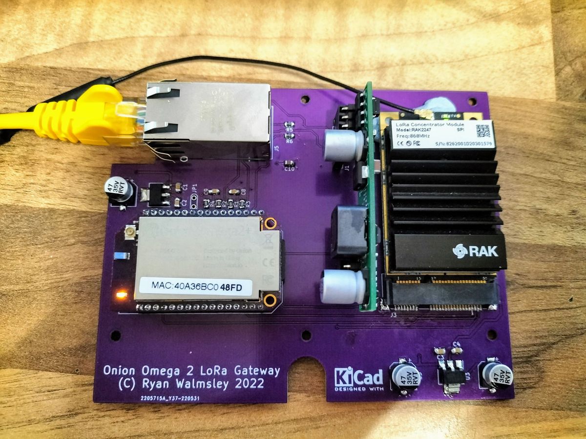
Resulting in this.

I then began testing by connecting my POE injector without any modules plugged in to check for shorts and all was fine, I then added the POE module and that worked well. After checking the voltages on the regulator I first tested with the Onion inserted, and then added the LoRa module on.
However there was an issue, the ethernet on the Onion wasn't working. Luckily after a little debugging I found it was just a bridge on the header that I soldered for the onion module connecting RX + & - together. After unbridging that it worked.
The Final Piece

After resolving the ethernet issue it was complete! Working first time which I'm very happy with.
Finally it was a case of putting it into the case itself. Which all the holes aligned first time!

Now all I need to do is get some new screws and mounting posts for it, otherwise I'm quite happy.
The resulting budget is roughly £200-250 per unit all in all which I think for an outdoor LoRa gateway is quite good. There's cheaper indoor units but I haven't found a good outdoor unit at this price.
What's next?
Next up on the to-do list is getting basics station to work and trying it with SEEED studio's SX1302 module. I don't expect too much of an issue with these so that should be fine.
After that I'm not sure if I'm going to open source the design, at the same time I may look at doing some small batches of the PCBs with base components soldered on. If you are interested ping me a tweet @Ryanteck to let me know and if there's enough interest I'll consider it.