So in one of my previous posts I did a review of a new EV charger I got that was meant to support Solar charging, TL;DR It's implementation was rubbish and didn't account for charging from export only.
Disclaimer
This is documented for educational purposes only, you may risk causing damage to your EVSE Equipment And / Or your Electric Vehicle. I am also not sharing any of the code at this time to avoid any issues with the code developed by the manufactuer of the charger. Overall this has actually been a project that's been on & off for a few months but due to a veriaty of reasons got delayed.
Lets Begin
The obvious solution to this is replacing it with another charger, however that's then more costs involved unfortunately so not ideal.
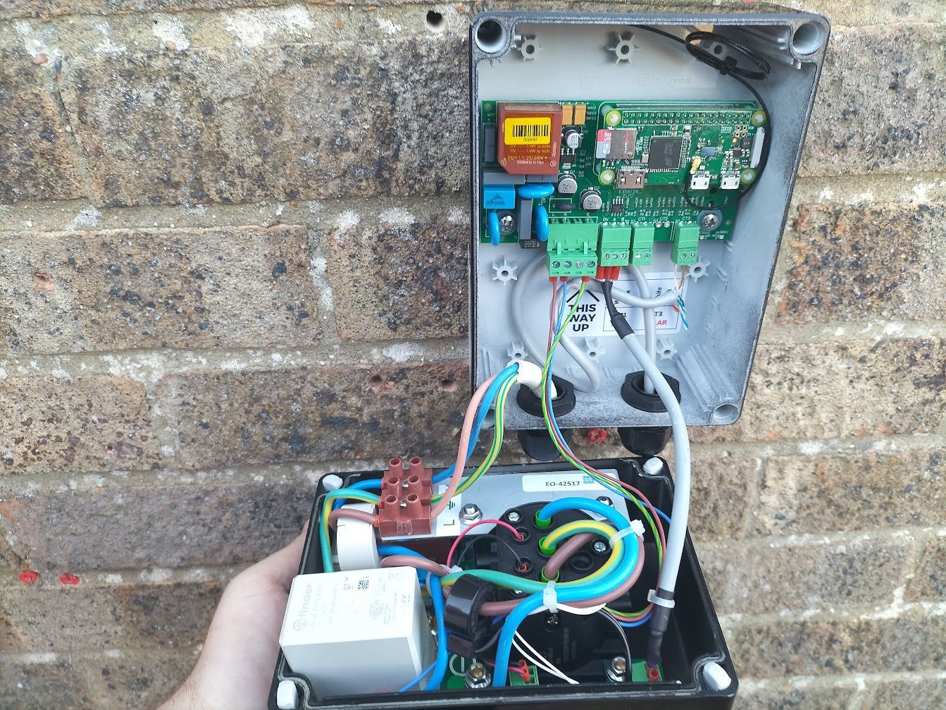
However, part of why I purchased the original charger that I did was that I saw the "smarts" of the charger were powered by a Raspberry Pi Zero so knew it was hackable from the start.
Handily because of the design of the charger having the "Smarts" done by this daughter Pi board, it left a dumb EVSE board to be communicated with requiring no modifications to that side.
Figuring out how it communicates
I knew at an initial guess it'd be some kind of serial protocol as the cable that went between the main board and the Raspberry Pi itself was only 3 wires marked GND, A & B. This then lead to it being either UART or RS485 of which it was the latter.
I sshd into the Pi, killed all the services of the software that was running on it and opened a serial port up at a few different baudrates with the RPi's internal serial port but just wasn't getting anything.
I had even tried running some of the code on the Pi itself that used the serial port and that also didn't work.
After some more hunting, I found mentions of the code using SPI for the RS485 which was confusing me so I dug up one of the pictures of the smart board itself.
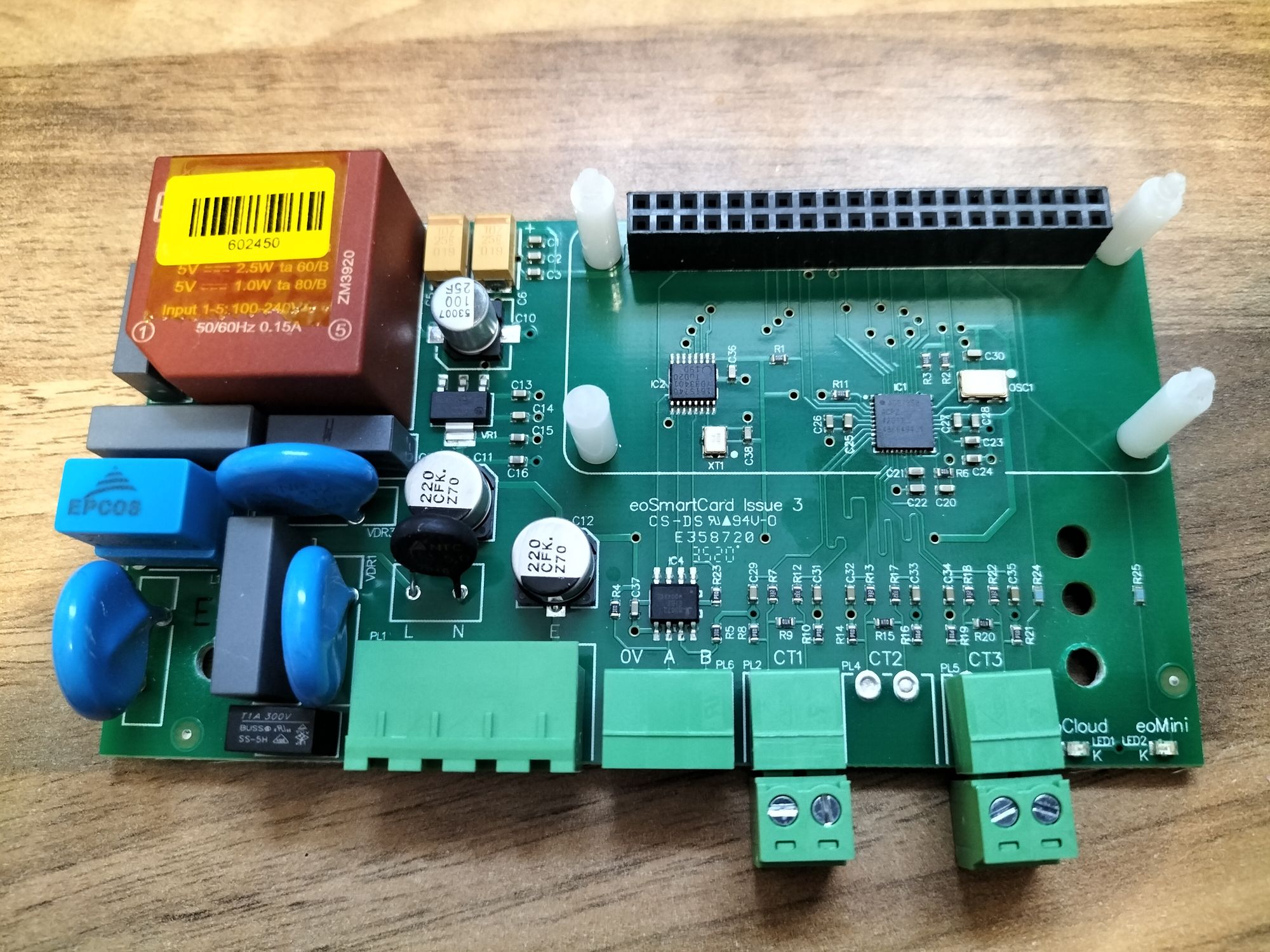
There's a chip directly above the 0V, A & B which seems to be a RS485 to UART converter which is excellent, but this then leads into another chip above. After some hunting I found that it seems to be a SC16IS740 UART with I2C/SPI Interface chip.
I'm not quite sure why you'd use a SPI to UART chip when the Pi has an onboard UART adaptor, maybe it's a conflict between using the Bluetooth on the Pi Zero W but it's not in use so I'm not sure.
Because of this and the fact I didn't want to use any of the existing code I decided to use a USB To RS485 converter instead and via cable connected it to another computer.
Unfortunately the code itself on the Pi was rather confusing (and very outdated version of Debian), there almost seemed to be 3-4 different programs that they had written to communicate with. The only one that seemed handy was one that was a test program that showed the command to send over RS485 to ensure the connection was correct.
This command was essentially in this form of just a few characters, starting with a > and then a few numbers. e.g >000064. I tried a few things but had no luck apart from sending this command, I then changed the number and noticed that the response had changed.
Handily this test program also had a decoder for the response string, however even this didn't match up fully so took a bit of experimenting to try and match up albiet still not perfect.
I then remembered reading the charge specifications for the PWM Duty cycle of the SAE1772 standard that the formula for that was the charge rate (in Amps) / 0.6A * 10 got the duty cycle %. In this case reversing that number we had from above gets us 6, aka 6 Amps!
Therefore if we then calculate the correct way, full speed would be 32A resulting in 212, add on the preceeding 0s and we get `>000212`.
Knowing this I then connected up my car and started sending values for different ampages and it matched what the car was then charging at!
Calculating what we can charge at
One of the next steps is then calculating what the charger can charge at, to do this required a few additional sensors which I pipe into my Home Assistant Setup
- Charger Current Power - This I done by having an ESP8266 & CT Clamp on the power running to the charger to provide me with the current wattage the car is pulling. (Guide)
- House Power Usage - The current way I do this is using a Glowmarkt Glowstick, this connects to my MQTT instance and provides a roughly real time figure of how much wattage the house is importing / exporting. The important thing here is the export figure.
Next we do some MATH(S), and simply just subtract the cars power consumption to the house's figure and we get the correct value. With a few examples being:
- -1.5kWHouse - 0kW Car = -1.5kW available to charge with.
- -0.5kW House - 1Kw Car = -1.5kW available to charge with, so it would increase to 1.5kW.
- 0.5kW House - 1kW Car = 1kW, so it would then decrease the car to 1kW.
Amazingly this from my testing so far is stable enough so it doesn't get into a loop of increasing & decreasing rapidly.
Next I then calculate an average, admittidly via a cheat method of adding the calculated value to an array in the python code for this loop that runs every 5 seconds, and popping the first item in the array after it hits a length greater than 50. This roughly gives us the average value the car should charge at over a 4 minute period, one of the benefits of this is if there's a slight cloud or if I boil the kettle for a cup of tea the car doesn't immediately stop charging.
I then like to keep a buffer of which I've set to 150W to smooth out the more frequent up and downs, so I then add 150W to the average figure. This means that ideally we should always export a little allowing for a buffer, rather than the other way around. So if we get 1.75kW from our average figure it'll set the car to charge at ~ 1.6kW.
Finally with that new figure I then need to convert it from watts to amps to send to the charger, to do this I simply invert the average value (from -1600 to 1600), divide it by the rough mains voltage in the UK (240), times that figure by 4, floor it and divide the final figure by 4. This way it then returns the ampage in a 0.25A step. floor((-average / 240)*4)/4
I could possibly not do this additional flooring & rounding to the nearest quarter, however I've found doing this also helps with providing a little additional buffer on top of the 150W we set.
Merging this together
So above we've calculated both how much we can export at, whilst also calculating how to control the charger so I just needed to combine it together.
To do this I essentially wrote two functions in python to run as a thread each, the first thread does the calculation of how much the charger should let the car pull and then the second sends the allowed current to the charger. At the same time I've also added an override feature to the code that controls the charger so if an entity on my Hassio instance is enabled it will then charge at full rate allowing me to then charge overnight if needed.
Testing
So all of the code was ready to go, I knew that control of the charger worked as I was able to charge my car at night with the override I programmed in and an automation in Hassio To Enable / Disable it. The next stage was waiting for a sunny day which currently in the UK hasn't been often.
However the day then came, the code kicked in and told the charger to start charging the car and.... Nothing. I then went and unplugged & plugged the car back in and it started charging!
From this and a bit of further testing I then gathered that the car was going to sleep and unfortunately the charger wasn't telling it to wake back up correctly, I had an idea of using a relay between the Control Pilot wire (the signal wire between the car & charger) to essentially trigger this for me which is something I did in a past hack with a different charger. However upon opening the charger I noticed a header that had Suspend next to it and with some googling found that this was so you could wire it into an economy 7 circuit using a relay to control if it should charge or not. Perfect!
I then just used a ESP8266 with a relay board and ESPHome to control it, then added the ability to control the relay from my python program to turn it on when charging shouldn't happen. And then turn off the relay when charging should happen (breaking the connection that enables the limit).
And with that set it was ready for round 2 of testing.
The Results
I ran my car down to around 65% by the day we were due to have a decent amount of solar production and had plugged it in the night before.
On the day at around about 10AM the code kicked in and started charging the car!
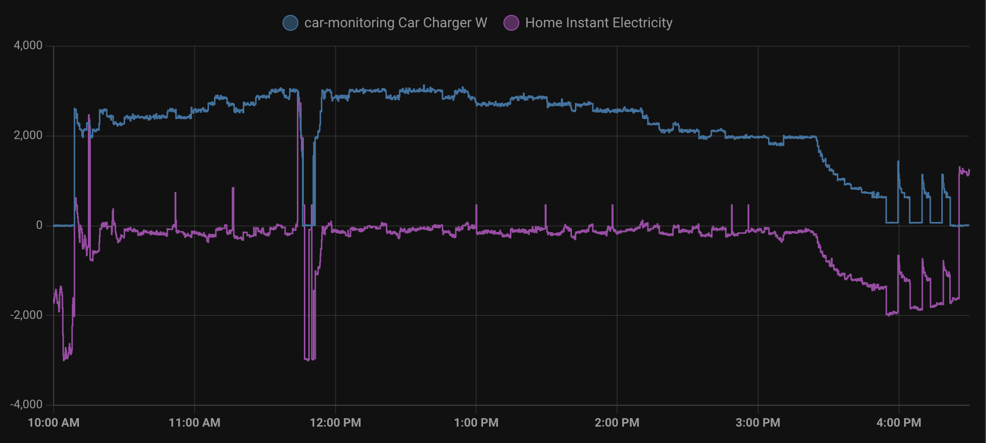
From around the 10Am mark we can see the house export drop as the car charging kicks in, it takes about 15 minutes but then settles into an approximate 100-200W export on the house whilst charging the car at just over 2kW. There's a few spikes throughout the day where we imported a little however due to the averaging code the car continued to charge like I expected.
At just before 12Pm a load did kick in for around about 15 minutes which stopped the car from charging, but the car then did resume as expected and charged the car fully.
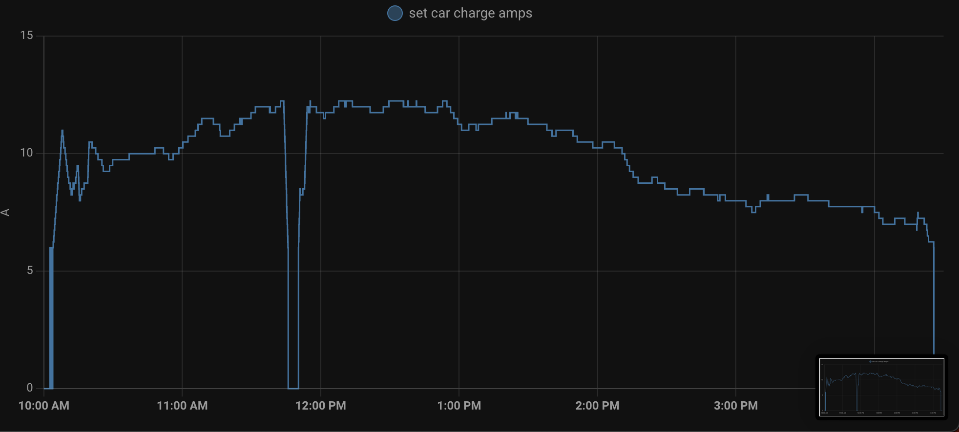
Analysing the ampage that the code set the charger to charge at we can see a similar pattern in the up and down, until around 3:45PM when the car was mostly finished charging and just balancing the batteries.
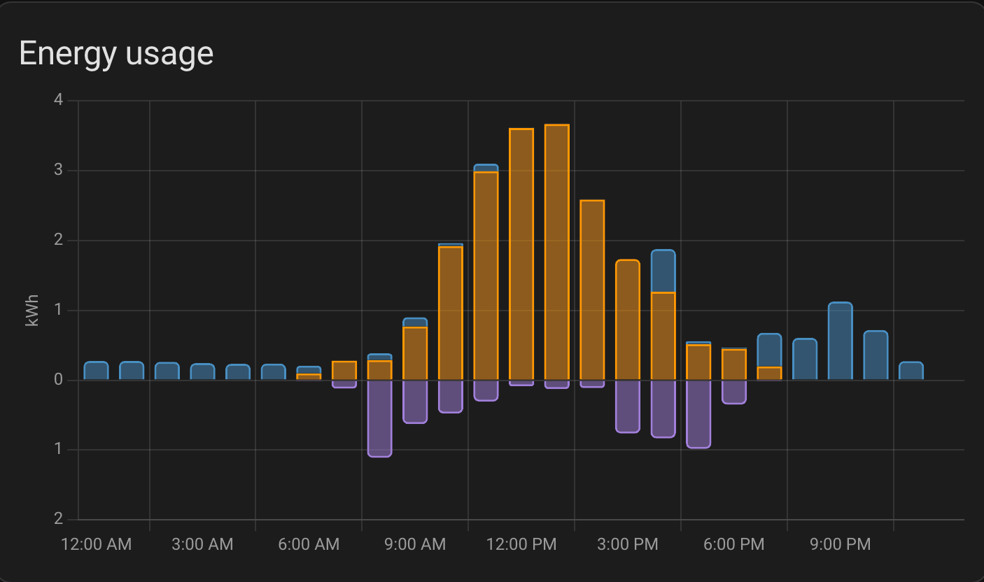
And finally then if I take a look at my house's power consumption for the day, we can see a near perfect graph where we used most of the solar production up for the day rather than exporting it, except for a couple of tiny blips during the period the car was charging.
Overall I would say this is a great success, over time hopefully I'll be able to shift more of my charging into times where we're producing enough solar. One thing with our system is whilst it's able to produce 5.25kW at peak, it's a split East / West installation so we rarely have ever seen more than 3kW on the best day and the minimum we need to produce for the car to charge is roughly 2kW (average 500W house usage and ~1.5kW to then charge the car).
Future Improvements
Whilst it's mostly working there are a couple of tweaks needed to the code over time, one of the main ones being that I need to handle when the connection to home assistant goes down better so that it doesn't crash. I'm also considering making a little PCB and moving it to run on a Pi instead in a neater format.